
This tutorial is an in-depth explanation of how to make PCBs on X-Carve. It will explore 2 different methods for making PCBs, Using FlatCAM and Chilipeppr.
This tutorial will cover a single sided board, but also explain out to go about making a double sided board, along with making drill holes.
1 minute
Before starting, there are some very important things to keep in mind.
-It is very important to minimize run-out . In simple terms, its the amount of ‘wobble’ the bit has. When milling a circuit board, the run-out is less then you can tell by eye. The higher quality the spindle, usually the less run-out you have. For these boards I am using the 400W quiet cut spindle.
-It is also very important to have a level build surface. The easiest way to do this is to follow the ‘optional’ auto-leveling later on. The thickness of 1oz copper is ~0.035mm thick. By comparison, a standard sheet of A4 paper is about 0.05mm thick. Thats pretty small! Even a 1/100th of a millimeter difference can make a huge difference when trying to route a PCB.
-Speed makes a difference. Too fast, you’ll break your bit. Too slow, and you’ll heat up your bit, causing excessive wear, and thermal expansion of the bit. Check out the end of the post here if you want to see some of the math behind this. I stopped by the local home depot and got this , to use as a kind of lubricant. Since it is waxy, it doesn’t run off the board or get easily pushed off from the spinning bit.
-I found the Dewalt 660, which was originally on the 31" X-Carve, didnt work nearly as well as the 400W Quiet cut spindle. Your results might differ, but I found I had to switch the Dewalt 660 out for the Quiet cut spindle to get nice cuts.
-Lastly, you need patience. Don’t expect to get it right in the first go (at least not for the fine pitch PCB milling). Trying to do small 0402 or SSOP packages is tough, and even 1/1000th of a millimeter of run-out can make a significant difference. If you can, try to leave extra room on your PCBs to account for run-out.
1 minute
As you should before any project, first step is to make sure you have all your materials!
Tools/Materials required:
PCBs
Clamps
Engraving bits
MDF Wood – Needed if planning to do double sided boards
Double Sided tape/Single short screw (<1/8") – Needed to hold board to MDF board, if doing double sided boards
End Mills – Needed to cut out your circuit board after engraving.
Optional tools to have:
Beeswax – Acts as lubrication while cutting
Wire + Probs – Used to setup auto-leveling
Multimeter – Helps to get milling bit at proper height, and test if traces are isolated after cutting
High Grain sandpaper – I used 1000grit. Used to clean up any edges from either engraving or cutting the circuit board out.
Isopropyl Alcohol – Cleans up the circuit board after milling, before soldering components
First, I’ll cover what programs you will need, and where to find out example files. Then I’ll step you through using FlatCAM to make your Gcode, and optionally using Chilipeppr to level your board. Next will be setting up your workplace and routing. Finally, I’ll finish off with some suggestions on further steps you can take to really make those PCBs outstanding.
EDIT 9/7/2015:
Inventables is currently out of stock of PCB milling bits, but you can easily find these bits elsewhere. I liked these 30deg 0.1mm bits and these straight bits for larger traces.
5 minutes
This project will be using the following board from Sparkfun as an example. If you use your own board, you may have more or less work then what follows.
SparkFun FTDI Basic Breakout – 5V
Shortcut to files:
(Eagle Files)
If you don’t have Eagle, you can get it here
To make the toolpaths, you will need a program called FlatCAM
If you want to auto-level your board before engraving, you will need to setup Chilipeppr
Note:
Chilipeppr will also do some PCB milling, but is fairly limited in its capabilities. FlatCAM offers alot more options/flexibility.
5 minutes
In order engrave your circuit board, you will need ‘gerber’ files. These are all the files that define what gets cut, where drill holes are place, where components go, etc.
To start with, open the .brd file with eagle.
Go to File→CAM Processor…
In the new window, go to File→Open→Job…
Select the file called “gerb274x.cam”.
-This is one of the default job files. If you have your own custom one, go ahead and use it here.
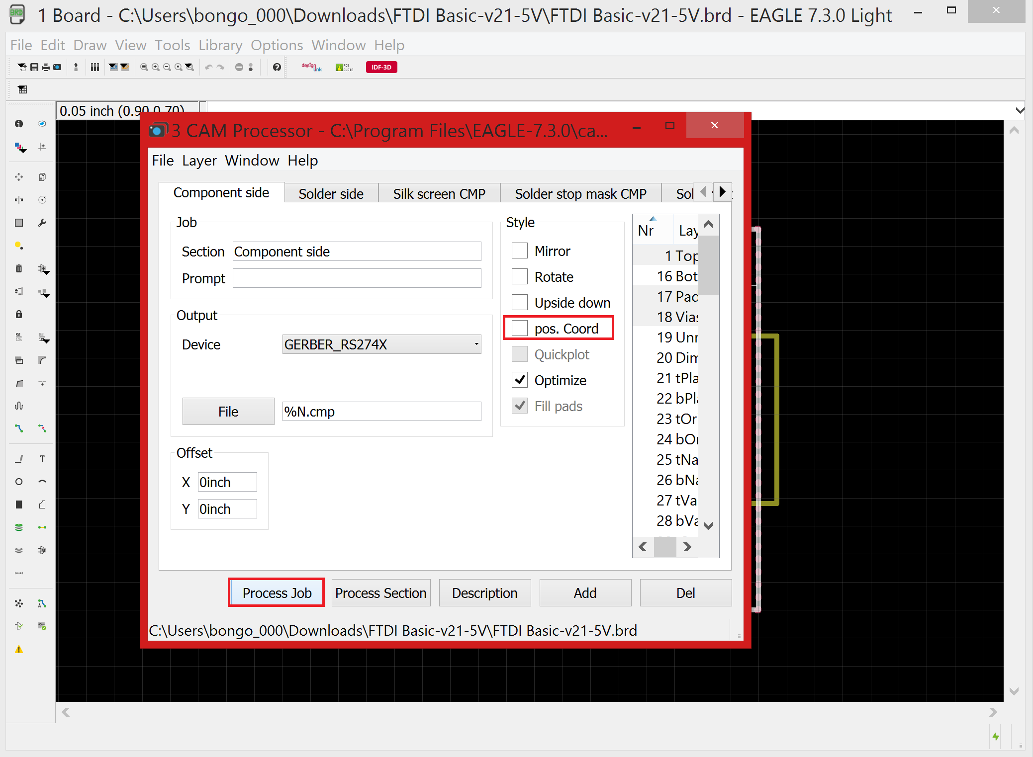
Now you’ll notice that there several files ready to be processed and exported. Before you run the job, deselect “pos. Coord”. Switch to Solder Side, and do the same thing. Now go ahead and select “Process Job”. This will export all the files into the same folder as your .brd file.
Now we have the component side and solder side files. If you plan on drilling vias and holes, you will want to do the above again, but select the “excellon.cam”.

10 minutes
Lets start off with a quick note. FlatCAM has several tabs, labeled:
-“Project”
-“Selected”
-“Options”
-“Tool”
All your files, toolpaths, jobs show up in the Project tab.
The Selected tab will change contents based on what you select in the Project tab. This means you HAVE to click back to Project tab in order to select toolpaths you made off your board file.
Options stores all your default settings. For this tutorial, just make sure the units are set to mm.
For more information, you can check out FlatCAM’s tutorial here .
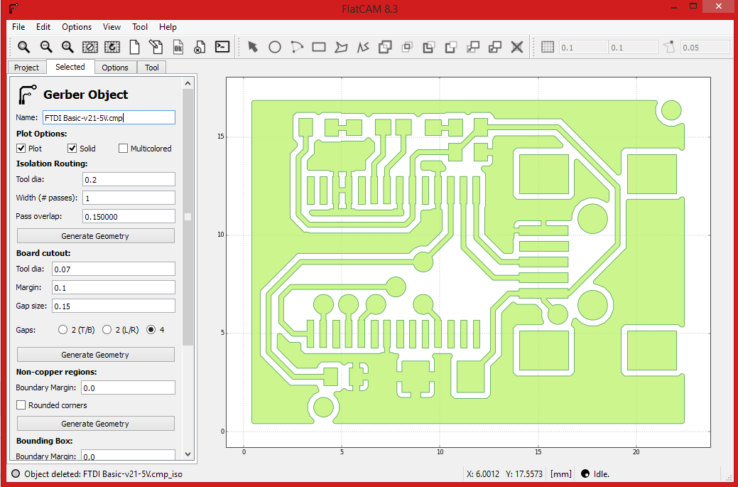
Now its time to import your files into FlatCAM.
File → Import Gerbers… and select the file that ends with .cmp you exported in the previous step.
Make sure you select the file you just imported into FlatCAM before clicking the “Selected” tab.
In this board we have some non-copper regions that we want to clear out, so there are a few extra steps. If you just want to cutout traces in pads, with no non-copper regions, you can use isolation routing in the next step and skip the rest of this step.
Now, on the “Selected” tab, scroll down to Non-copper regions. Put in ‘0.25’ . Click Generate.
Go back to “Project” tab, select FILENAME_noncopper, and now back to the “Selected” tab. Scroll down to the Paint Area section. Insert the tool diameter and overlap. I used 0.25 for both. Its usually a good idea to oversize your tool bit, even a fraction off of height or too much runout will drastically increase your effective tool diameter. If you end up cutting off too much later on, come back to this step and increase your tool diameter.
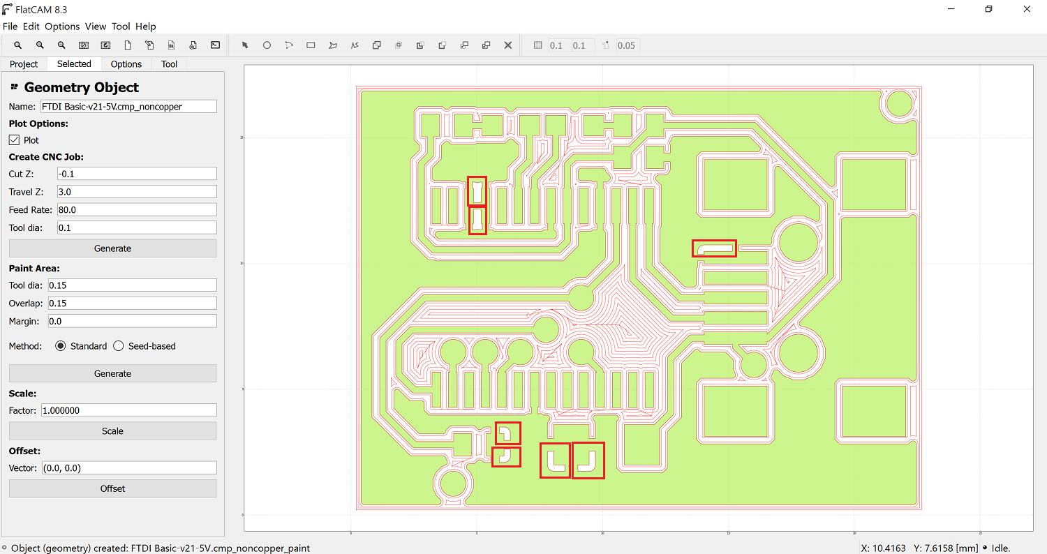
Once you click generate, select inside the largest non-copper area. It will auto-generate a path that cuts out the majority of copper. There are some small areas that it doesn’t cut, I have attached a picture showing where they are. Select generate then click inside, for each of the areas shown in the picture.
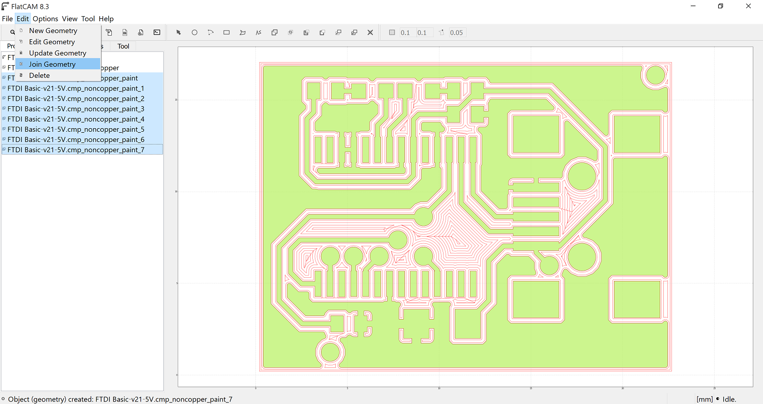
Go back to “Project” tab. You will now have a bunch of FILENAME_noncopper_paint_# files. Shift select all of them. Once selected, go to Edit → Join Geometry. A new file called ‘Combo’ will appear. Selected, and switch to the “Selected” tab.
On the “Selected” tab, scroll down to the Create CNC job section. The boards from Inventables are 1oz copper, which is ~0.035mm thick.
-You want to make sure to cut through the copper, so put 0.04mm-0.05mm into the Cut Z.
-The Travel Z is the height above the copper the spindle will travel, so use 1-3mm.
-For a quiet cut spindle, use 70-80mm for Feedrate. For the routers, they go quite a bit faster, so use 150-200mm instead. Feel free to fiddle with these Feedrates to try and get better results.
-For tool diameter, use 0.1.
Finally, click generate.
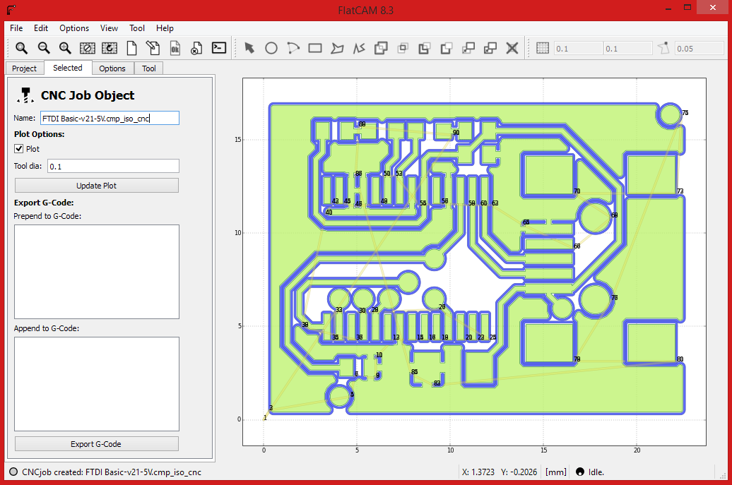
Last step. Go back to the “Project” tab, select Combo_cnc, and back to the “Selected” tab. Export your G-Code.
IMPORTANT
Almost all the above variables are dependent on your machine. You may find your machine has less runout then mine, or more. You can cut a little deeper using a 15deg bit vs. a 30deg bit, without messing up traces. You also may be able to cut faster using active cooling, or need to cut slower due to the router running hot. The numbers here are really just a starting point, and they will likely need adjustment based on your situation.


10 minutes
In the previous step, I went over only using the non-copper regions tool, as it also does the isolation routing. If you only want to do isolation routing (I.E. only cutting the traces and pads out, and not cutting out large areas of copper), then you can follow this step instead.
On the “Selected” tab, scroll down to Isolation Routing. Put in ‘0.25’ for tool diameter, 1 for # of passes, and 0.15 for Pass overlap. Click Generate Geometry.
Go back to “Project” tab, select FILENAME_iso, and now back to the “Selected” tab.
On the “Selected” tab, scroll down to the Create CNC job section. The boards from Inventables are 1oz copper, which is ~0.035mm thick.
-You want to make sure to cut through the copper, so put 0.04mm-0.05mm into the Cut Z.
-The Travel Z is the height above the copper the spindle will travel, so use 1-3mm.
-For a quiet cut spindle, use 70-80mm for Feedrate. For the routers, they go quite a bit faster, so use 150-200mm instead. Feel free to fiddle with these Feedrates to try and get better results.
-For tool diameter, use 0.1.
Finally, click generate.
Last step. Go back to the “Project” tab, select FILENAME_iso_cnc, and back to the “Selected” tab. Export your G-Code.
IMPORTANT
Almost all the above variables are dependent on your machine. You may find your machine has less runout then mine, or more. You can cut a little deeper using a 15deg bit vs. a 30deg bit, without messing up traces. You also may be able to cut faster using active cooling, or need to cut slower due to the router running hot. The numbers here are really just a starting point, and they will likely need adjustment based on your situation.

30 minutes
If you decided to cut your board out first, keep reading. If not, you can skip this step.
This part will let you cut out the SOL side of the board (the bottom). If you just want to test out your engraving, or only have a single sided board, you can skip this step.
Inventables only allows 1 Easel link per tutorial, so I have included the links you need for cutting out the Board and the Fixture in this step.
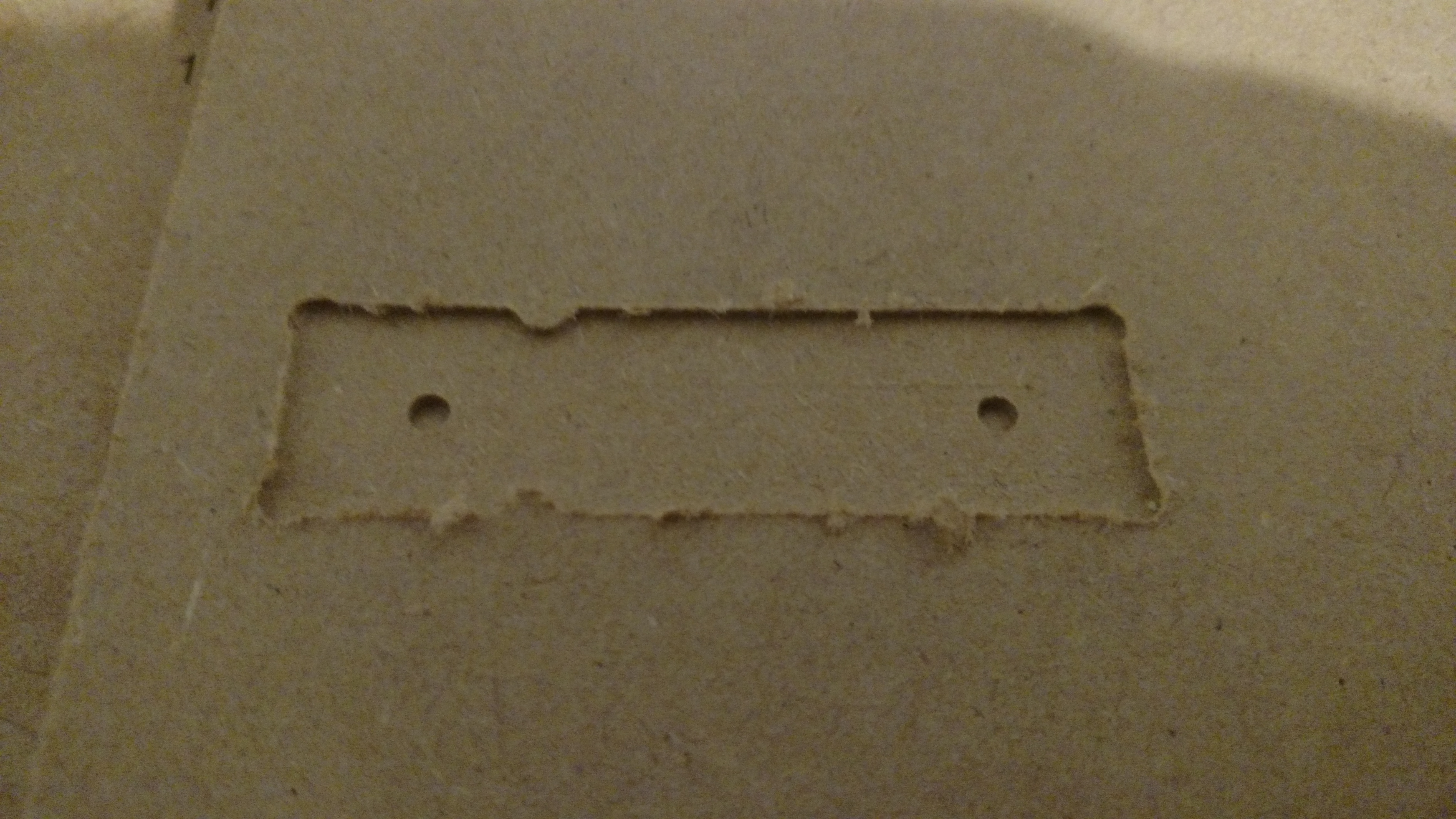
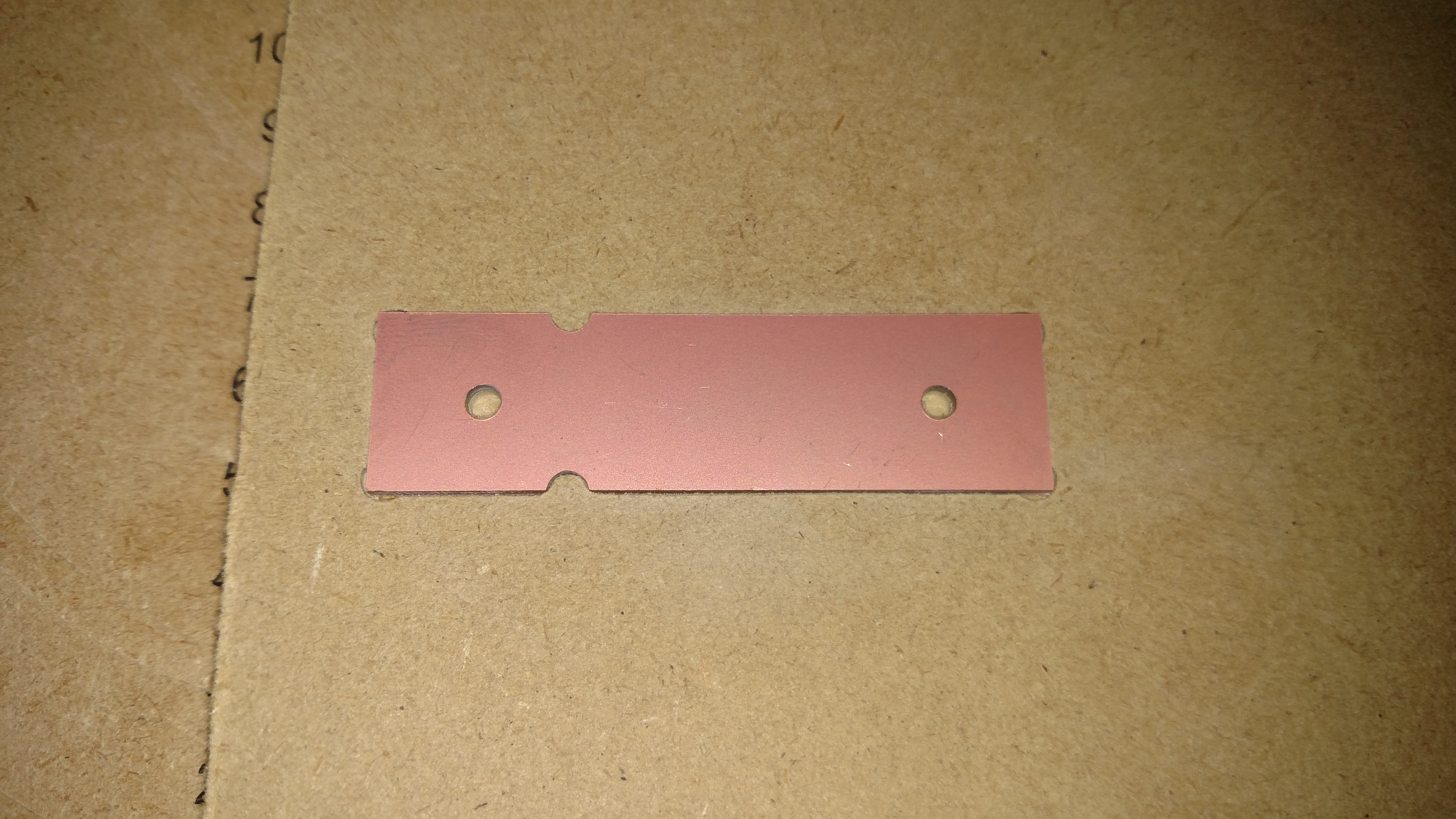
Note that the board and the MDF cutout have a hole. This is to fixture the board to the MDF. Double-sided tape works okay, but for added measure, you can use a screw through this hole into the MDF to ensure the PCB stays in. Note that the warping that the screw may cause will be filtered out when running the Auto-level function in Chilipeppr.
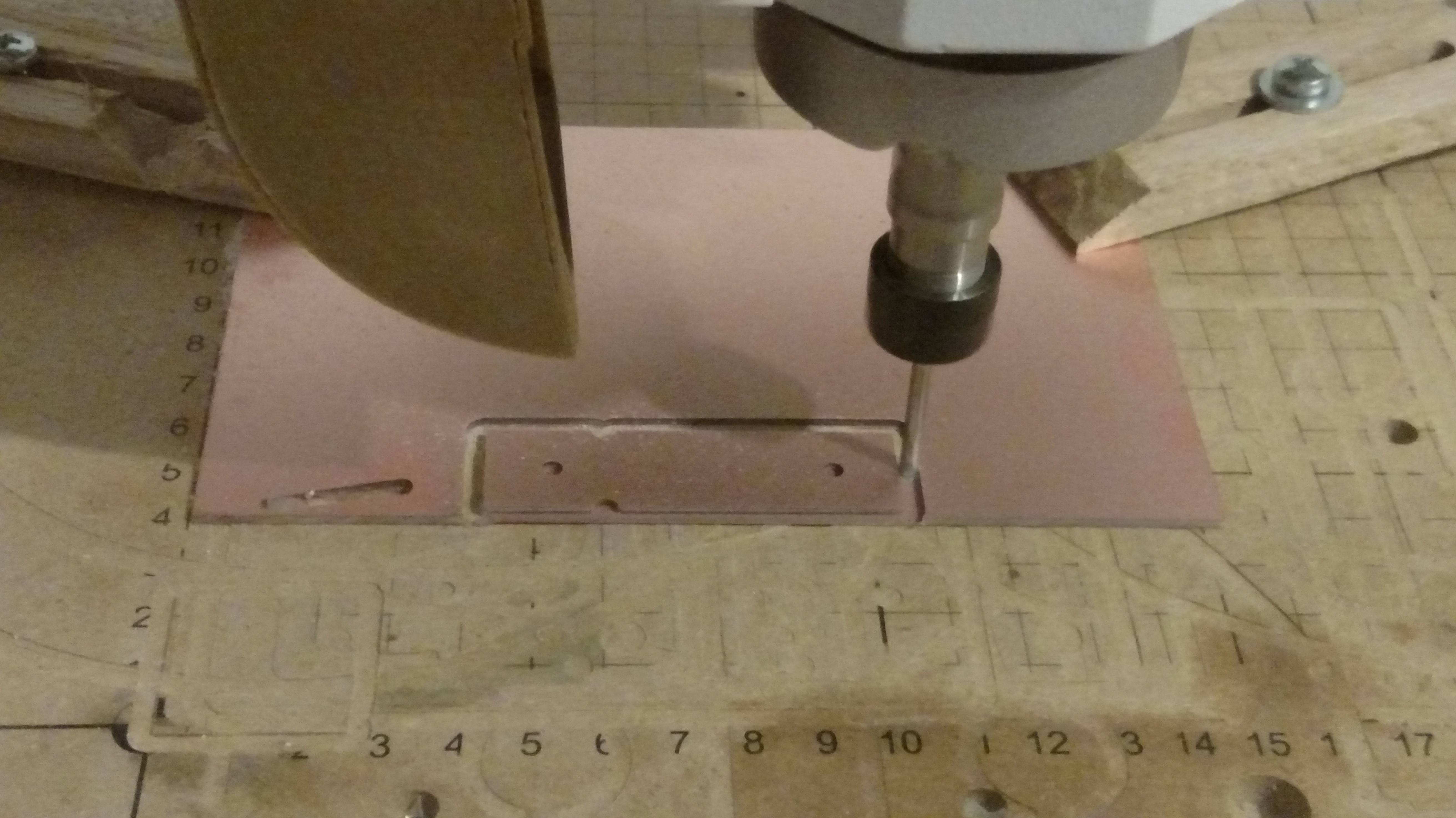
First set up your PCB. Start your bit at (0,0,0), as close as you can, it doesn’t have to be perfect. Use the Easel project for the board to cut out your PCB.
After clearing the workspace, set up your MDF block. Again start your bit at (0,0,0), as close as you can. This time, use the Easel project for the fixture. After this is done, DO NOT REMOVE FIXTURE. The area that has been cut out is perfectly aligned now with your machine, ensuring your PCB doesn’t get engraved at an angle. Note that it is okay to turn off your machine after this, just don’t move it around by hand.
You can now place your PCB in your fixture! It may be a tight fit, but this will make sure your part stays nice and still during the next part.
Switch out your bit to the engraving bit for the next (next) step.


5 minutes
If you don’t cut your board out first, and just want to go straight to engraving, keep reading. If not, read the previous step.
This is a super simple setup.
Fixture your PCB to the workspace.
Thats it! On to the next step!
(Note: Make sure its straight, clamped tight, etc etc)
5 minutes
Setting up Chilipeppr is pretty simple, but I am going to go over it real quick here.
First, visit http://chilipeppr.com/
From here, select the Grbl workspace.
To start with, navigate to the bottom right window, ‘Serial Port JSON Server’. Switch to the Your Servers tab, which will provide you with links to download the server exe.
After downloading the zip file, go ahead and run the exe. (Make sure your machine is on and connected when doing this). I am using Windows, so unsure what Linux/Mac users will see, but a small command prompt comes up with some info. One of the lines near the end lists out the COM ports, of which Grbl should be connected to (labelled as Arduino).
Move back to the ‘Port List’ tab in Chilipeppr. Here you should now see your machine. For Grbl, it is VERY IMPORTANT that you select in the first dropdown list ‘grbl’, before connecting. To connect, just click on the small box to the left of the picture of the Arduino.
That’s it! You are now connected to your X-Carve with Chilipeppr.
15 minutes
This is an optional step that uses Chilipeppr to auto-level the board, or the gcode you made in FlatCAM. It requires some additional set up. This is purely optional, but it is HIGHLY SUGGESTED.
You will have to set up your machine to use the Zmin limit switch to detect when the bit is touching the copper surface of the board. See picture for example of how I did it. The 3d printed piece is available in the design files section.
For TinyG, one wire goes to Zmin, the other to ground.
For Grbl, one wire goes to pin A5, the other to ground. On the X-Carve, there isn’t a through-hole for this pin, so you will need a 0.100" header pin to plug directly into the Arduino board.
For running the Auto-Level tool in Chilipeppr, check out this nice tutorial .
Before you start, make sure all your probes are hooked up, your board is clamped/fixed, and your bit is at (0,0). This is right at the corner shown in the picture, if you used the fixture. The Z-height can be a bit higher then the board, 1-5mm. The first probe point will set the Z height to 0 at that point.
The quick summary of the above video:
-Connect to your X-Carve.
-Load your gcode into Chilipeppr.
-Select Auo-Level in top left.
-Adjust settings as necessary.
-Switch to ‘Run’ tab.
-Click the ‘play/send’ button. (Assumes you have made sure your circuit works with Test Probe already)
-Probe surface
-Switch to ‘Post-Run’ tab
-Select ‘Send Auto-Leveled Gcode to Workspace’
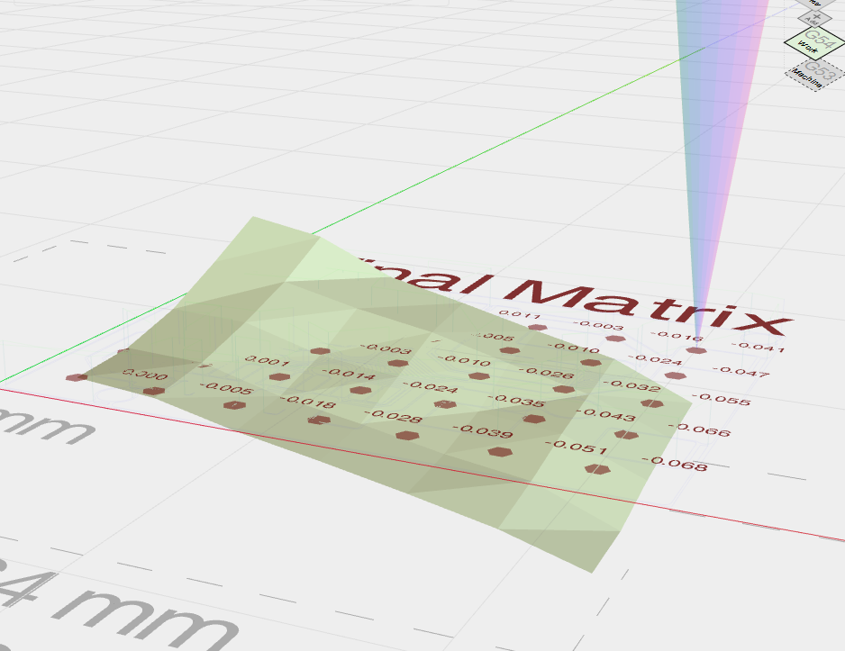
You can now send you leveled gcode to your workspace in the ‘Gcode’ window. If you want, you can scroll through it and look at the added ‘Z##’ values appended to compensate for un-even boards.
Some suggested settings are using 2-3mm spacing, and 10-15mm/min z feedrate. The more data points, the more accurate the map will be when it adjusts to match your board.
Note:
There have been wide reports of noise on these circuits, so I suggest a pullup resistor (~500Ohms) to 5V on Grbl or 3.3V on TinyG, and/or twisting your wires all the way up to your probes. I didn’t have problems with either board without it, so try it without to start with.


25 minutes
If you used Eagle+FlatCAM without auto-level, you can use your preferred gcode sender to send the code you generated in FlatCAM to the X-Carve. Make sure your bit is as close to the lower left hand corner of your board, (0,0,0) before sending. This is right at the corner shown in the picture, if you used the fixture. It is suggested that you use a Multimeter to test continuity between bit and board, and slowly lower until it just barely connects. This will ensure you start just barely touching the board.
If you decided to auto level your board before cutting, make sure you follow the video tutorial link there, which will show you how to send your new auto leveled gcode to your X-Carve. Your machine has already stored (0,0,0) when running the Auto-level feature, so just send your auto-leveled gcode and it will move back to 0,0,0 on its own.
10 minutes
Nearly there!
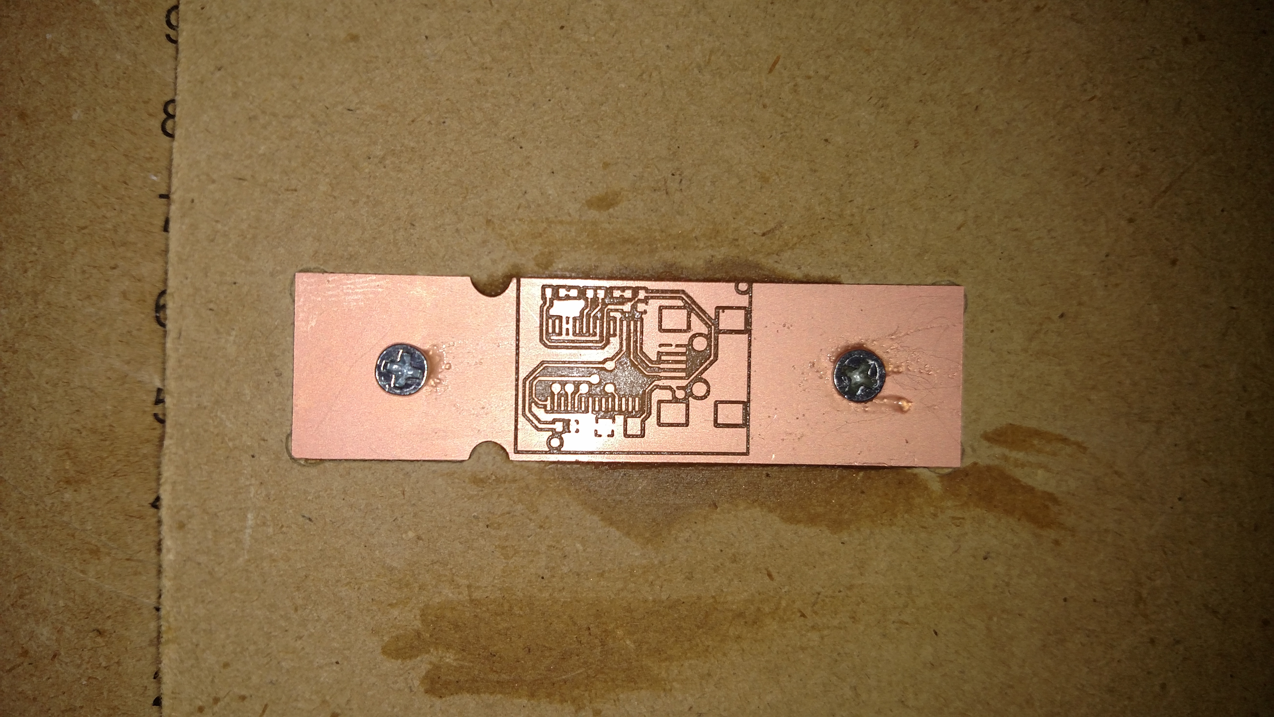
You can see the almost done product below (ignore the fact that I didnt line the board up quite right, that was user error…..)
If you want to engrave the bottom, or drill holes, skip to the next extra step.
Next, you need to cut the board out. If you have access to a bandsaw, it might be easier to use that. Otherwise, switch back to your 1/8" Endmill.
If you want to reuse your fixture, you will need to take off the circuit board and clamp the board down elsewhere. Otherwise, you can just keep the board screwed down and cut through the MDF while cutting through the board. For this board, I just manually oriented the machine, and manually entered Gcode commands. G1 Z-2 F75, then G1 Y20 F50. This will make a straight line up at 2inch/min, nice and slow to cut through the board in a single cut.
There you go! One engraved PCB.


1 minute
Now that you have finished this tutorial, some of the extra steps you can go to are engraving the second side, drilling the holes, and adding a soldermask before soldering components to the board.
If you followed the step that cuts out board and makes a fixture, you can just flip over the board and use FlatCAM’s double sided tool to etch out the second side, following the same steps as above but using the file ending in .sol . After cutting out the second side, you can drill holes (below). After that, you can either re-clamp your piece to your machine and cut off the excess that was used to fix to the MDF board, or use a bandsaw, etc. to cut it off.
To drill holes, you can import your Excellon file (file ending in .drd) that you exported from Eagle earlier. Note that Eagle suppresses leading zeros in you file, so you will have to open the file and make sure all the X#Y# are 5 digits. If any are 4 or less, add 0s in front to make it 5 digits. Save the file. Import the file into FlatCAM as an Excellon file. Eagle exports in mils, and while flatcam converts to mm, the scale is still off. Select your FILENAME.drd, switch to the “Selected” tab, and scale by 0.01 . All your holes should line up now! Reference FlatCAM manual here for the rest.
If you want to apply a soldermask to your board, you will need the following.
-UV Curable soldermask paste
-UV light
-Transparencies
The tutorial here is a quick video that demonstrates how this works.


10 minutes
Quick tip!
If you want to change bits between jobs, but keep your coordinates and proper height, its pretty easy using Chilipeppr. Note that you will need auto-level hooked up.
First and most importantly, DO NOT TURN OFF THE MACHINE. Doing this will always loose coordinates between jobs.
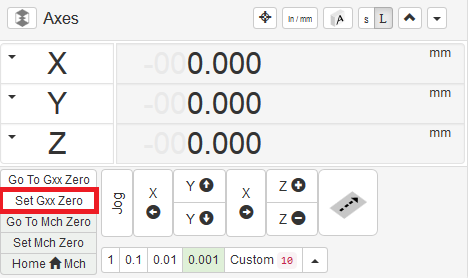
After completing the first job (say in this case the engraving), and your machine has moved back to (0,0), raise the Z-axis high enough that you can remove the bit. The manual controls are in the top right corner of Chilipeppr. Remove the bit from your spindle, and put in your new one. Lower the Z until you are relatively close to the board. Now go to Auto-Level → Run and click “Run Test Probe”. The machine will move the bit down until the probe makes contact with the circuit board. Once this happens, in the Axes window, click the Set Gxx (when connected to the machine it will say G54) Zero. This will set the work coordinates to (0,0,0).
You can now run your next job, like the drills, without worrying if you arn’t level with the board.
1 minute
Some things to keep in mind when trying to engrave PCBs:
-The smaller the spaces/packages, the harder it is going to be to get right! Sometimes you can’t help it, but when you can, try to give yourself some extra room between traces, and make your traces larger then necessary. This can save you some headache later if your runout is too high, you cut too deep, board isn’t perfectly level, etc. All of these could contribute to cutting too much copper away.
-When you can’t get away from the small spaces, remember to take your time before cutting! Going through all the steps of setting up a fixture, lining the board up, leveling, etc. can really make sure you arn’t going through 3 boards before you get one that you can use.
-Patience is key. Don’t expect to get it right the first time, or the second. Doing big boards takes even more time, so take the time to probe and engrave at the proper speeds.


Akhil S Nair
Mike Machado
John -
Chris May
Pete Mathews
keith h allen
Carlos Franceschini