
Michael Una
Chicago, USA
A shield for Arduino Nano with a ring of LEDs and four potentiometers, for making musical instruments or visual displays.
The first step is to create your board design. I won’t go into that can of worms here- if you need help getting started, I recommend this guide from Sparkfun: https://learn.sparkfun.com/tutorials/how-to-install-and-setup-eagle
That said, here are a few guidelines that will make things easier down the line:
- Make your traces and pads as fat as you can get away with. I find 0.04 works well for me.
- Use as few vias as you possibly can. You’ll be doing them by hand later, so be economical.
- Keep all your components to one side and all your traces to the other, as much as possible.

Once you’ve got the design completed, export three images of the board. Here are the layers each image should contain:
Drills: Pads and Vias
Top side: Pads, Vias, and Top layer
Bottom side: Pads, vias and Bottom layer
Make sure to export the exact board size and not your viewing window size- each image needs to have the exact same dimensions.

Bring the board images into your favorite vector drawing software and perform a trace operation to convert the bitmap raster image into vector lines.
I prefer Adobe Illustrator, so I use the live trace function. You’ll want to trace as a black and white image, set the threshold until it looks accurate, and set the tracing to follow paths as closely as possible and to use corners rather than curves.

This is an important step- you need to mirror the bottom layer horizontally. In Adobe Illustrator, there’s a function called Mirror that does this.
The reason is that when we get to carving the board, we have to flip it over for the bottom side. So the image needs to be flipped as well so that everything ends up in the right spot.
Easel can import an .svg file, so that’s what we’re going to use. Export the Drills, Top and Bottom traced vectors as .svg.
If you haven’t done so yet, go to Easel.com and create yourself a free account.
The next step is to import each of your .svgs as a separate file into Easel- Drills, Top Side, and Bottom Side.
Take a step back from the board for a second and consider how we’ll hold it in place to drill and carve both sides- we need to line up the first side and then flip the board over and place it exactly in the same spot to make sure the two sides line up correctly.
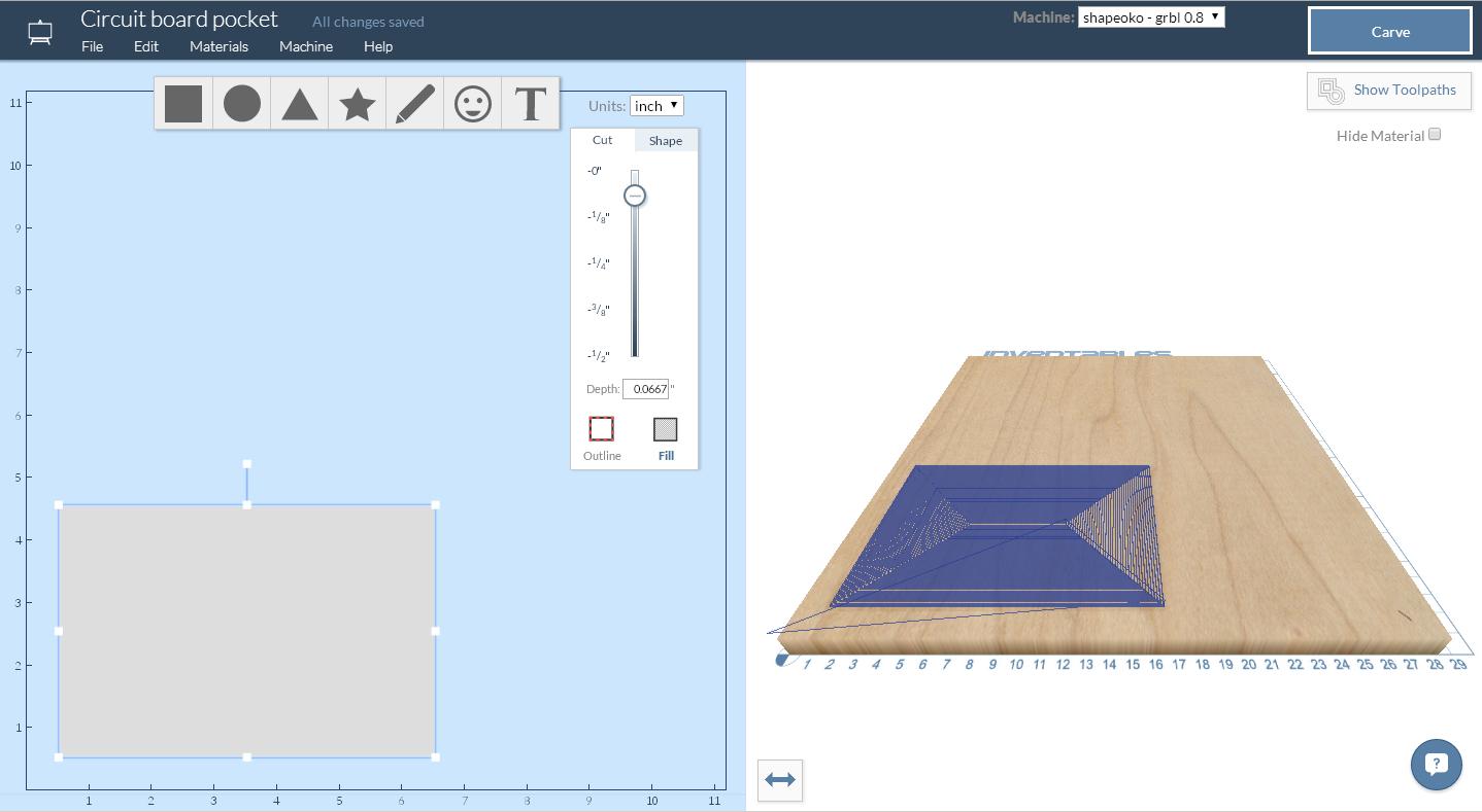
How do we do that? We use the machine to carve a pocket to hold the board in place. That way we know the pocket is square and aligned with the motion of the machine. Additionally, if we make the pocket exactly as deep as the circuit board material, we know that the top surface will be level for Carvey’s Smart Clamp.
Here’s my pocket, sized for a 4×6″ board: http://app.easel.com/projects/gemsutKpVan_WxMAGJzXdA
Load up the drills .svg into Easel and set the depth to go all the way through the board. Select a drill bit that’s just slightly wider than the thickest component leg you’ll be working with.
Mount your circuit board blank into the pocket you created in the last step using double-sided tape. I use regular Scotch double-sided tape, three strips running the length of the board. You don’t have to go crazy, just make sure the board stays put. Make sure the board is snug against the lower left corner of the pocket.
Here’s my file as an example: http://app.easel.com/projects/mA7tlgDzu3W_uz3d-VlKYg
Make sure you have “Copper” selected as the material, and change the bit size so Easel knows how big your drill bit is.
One thing you may nee dot do in this step is realize that you need to go back and adjust your pad sizes down so that they’re just barely big enough for the drill bit to fit into. Otherwise, Easel will attempt to remove the entire pad area and that isn’t what you want.
You can adjust the pad sizes either in Easel itself or in your vector drawing program. Just make sure you keep the center of the object as your point of positioning, otherwise your board won’t look right.

Keep the board where it is. Now we’re going to carve the top layer traces.
Change out the drill bit for your circuit board milling bit. I like the 20 degree, 0.01" tip but experiment and you’ll find what works for you.
Start a new Easel file and import the .svg for the top layer traces. Position everything in the same place as you did before. Select “copper” as your material, set the depth as 0.015", and make sure the cut is set to “Outline” and “Outside” the lines.
Make sure you set your bit size as 0.01", check that everything looks okay and then let it rip!

Now for the bottom- we’re almost there!
Use a small flathead screwdriver or spatula to carefully pry your board out of the pocket.
Remove the tape on the bottom, then apply new double-sided tape to the other side. Maker sure you’re flipping the board along the horizontal axis (not vertically!) and tape it down snug against the lower left corner.
Import your .svg into Easel and make sure you set everything the same as the top side- 0.01" bit size, 0.015" depth, outlines outside the lines, and in the right position. You might want to double-check that your traces are flipped horizontally as well.
Make sure everything looks ok, then click Carve and watch the machine work its magic.

If everything went smoothly, you now have a finished 2-sided board with all the traces and holes in the right place. Now you can start soldering in your components.
A few tips:
To make vias, use a small bit of wire or the remains of a trimmed component leg and stick it through the via hole. Solder one side, then flip the board and solder the other. You might have to bend one end into a hook to get it to stay in place while you tack it down.
Use as little solder as possible, work slowly, and be careful. Because there’s no solder mask on the board and a lot of copper surfaces, if you aren’t careful you can get solder all over the place.
And now you have enough knowledge to get started making your own 2-sided boards. Share your creations with us, we’d love to see what you come up with!


Michael Carroll
Michael Carroll
Matthew White
hobie thompson
Michael Parks
Frank Ramirez