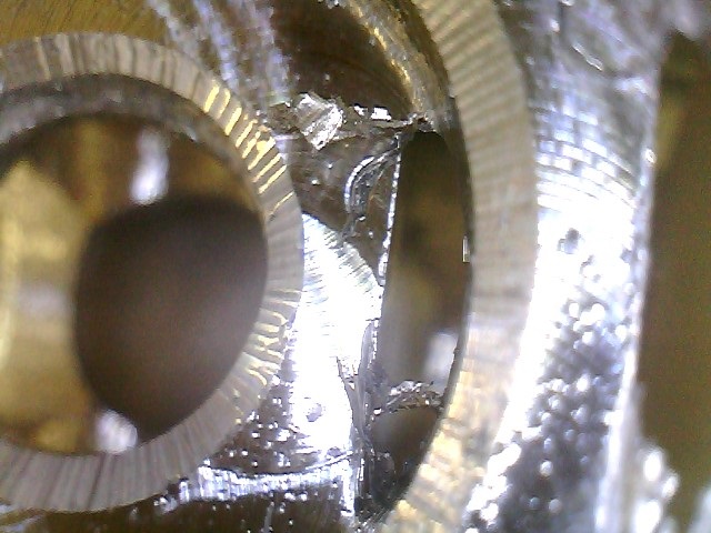
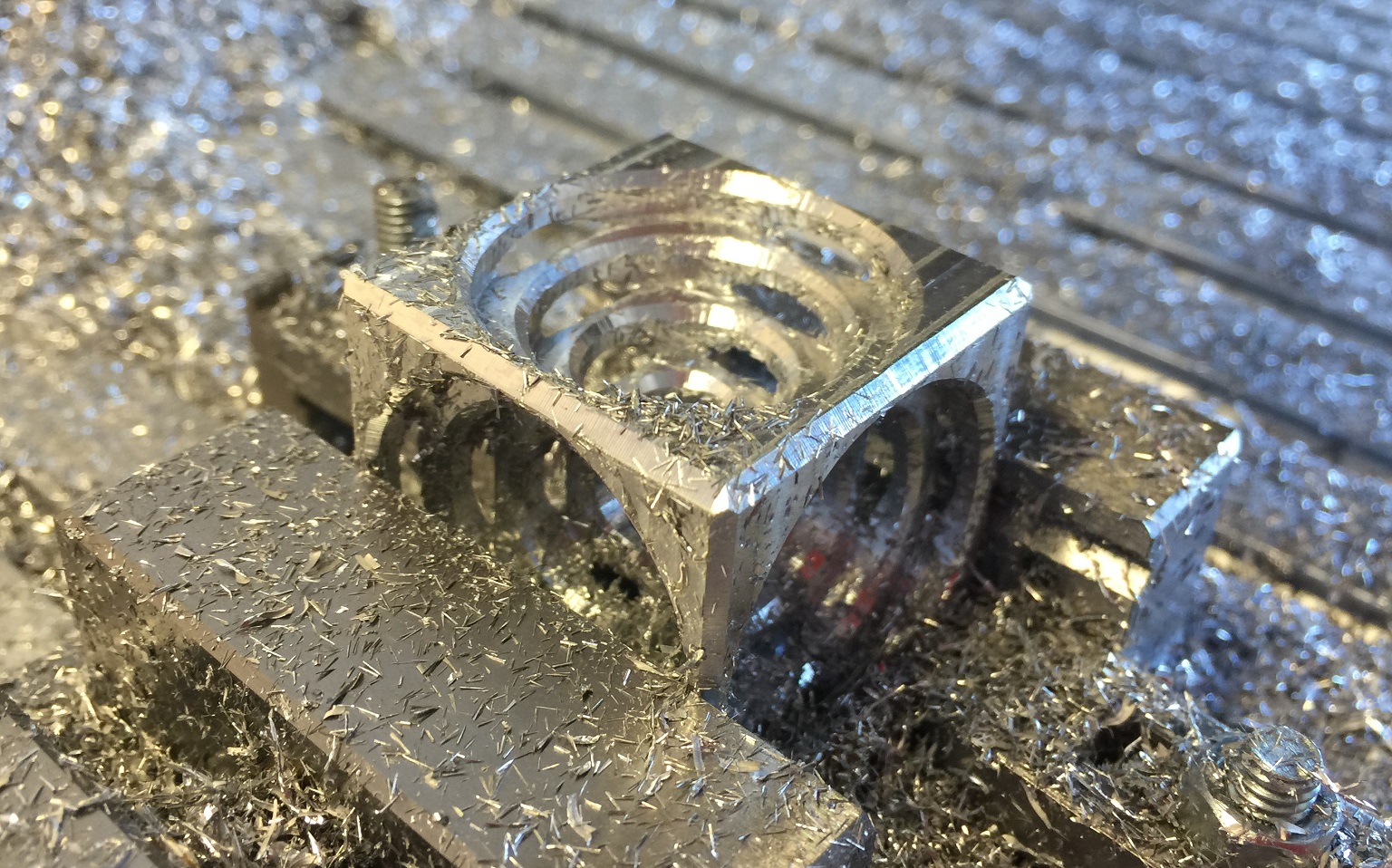
A nice aluminium cube with a stepped circular hole milled from each face. The negative space from the holes in each side intersect, and it looks like you have series of nested cubes.
1 minute
As this project is a little different from the standard Easel project, I wasn’t able to list the files and materials in the normal place.
The CAD and CAM is available in AutoDesk Fusion 360 at http://a360.co/1DFLXqr as well as an archive file in this project.
For materials, you will need some 1 1/2" aluminium bar stock. I purchased some from 6061dude on ebay (http://stores.ebay.com/Stoners-Tools-and-Raw-Materials/Aluminum-Square-Bar-/i.html?fsub=4524051017&sid=60426447&trksid=p4634.c0.m322). Pretty good prices and free shipping in the US for when you are just looking for a small amount of aluminium stock. You could also get some from McMaster Carr, or other suppliers.
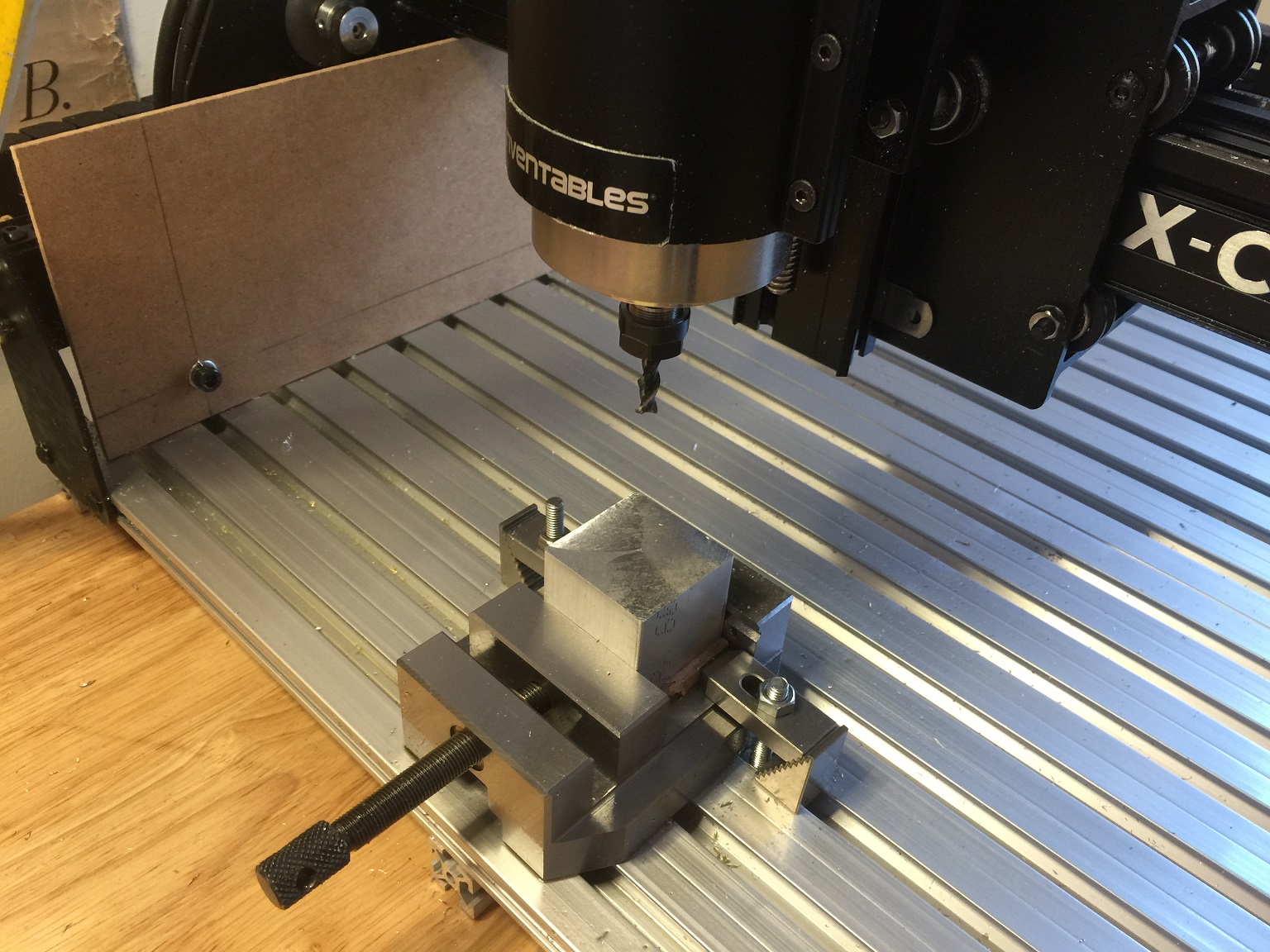
For the tools, I used an X-Carve CNC mill, that has been modified a bit. I added an aluminium T-Slot bed and a 800 W VFD Spindle. The bed upgrade is not a requirement, but you might have difficulty completing this project with the stock 300 W DC spindle. The VFD spindle or the Dewalt 611 would both be ideal for this project.
We are going to repeatedly run programs keeping the same work coordinate offsets, so we need the latest version of GRBL that does not have the bug that makes it lock up if sent an M30 command that Fusion 360 uses to mark the end of the program. I used version 0.9j.
I used a 1/4" 2 flute carbide “Viper” aluminium cutting bit from Destiny Tools to do most of the cutting. I also used a 1/4" carbide chamfer bit for aluminium from Online Carbide. If you use different sized bits, make sure you update the tools in the CAM section of Fusion 360 so that it generates the correct toolpaths.
In addition you will need some kind of saw to cut the aluminium bar stock. A table saw with a carbide tip blade or a band saw would work.
Finally you probably want some source of compressed air to clear chips. You could use canned air, but you might want to use a small compressor.
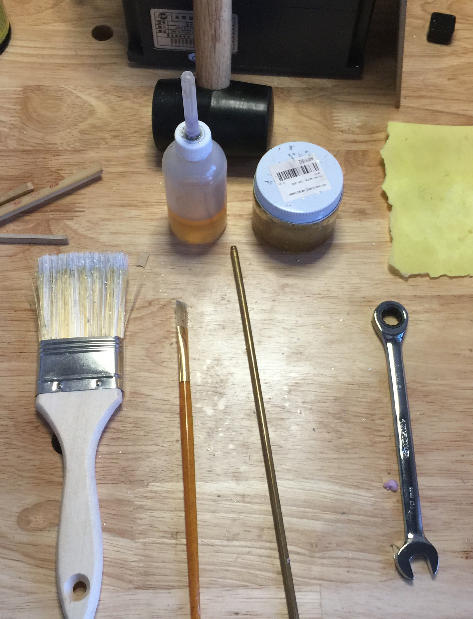
I also keep a few hand tools on hand to help out. Some of these are a chip brush (just a bristle paint brush), a dropper and brush for applying cutting oil, a 10mm wrench for adjusting step clamps, a rod for tightening and loosening the vise, and some paper for zeroing the height cutting bits.

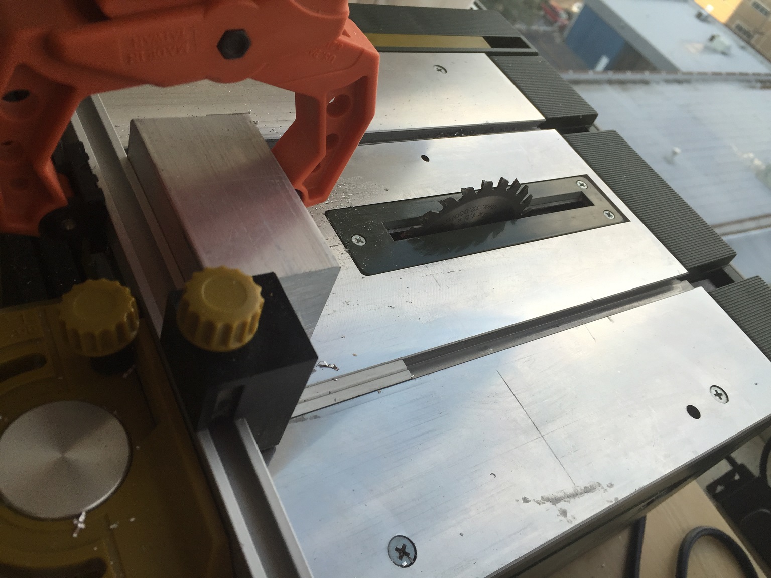
You need to cut bar down a rough cube. Your cut will probably be a little rough, so cutting it a mm or two longer than you need is a good idea, so aim for about 39mm. My little table saw can’t raise the blade a full 1.5" inches to make the cut in one pass, and I didn’t want to cut through my miter fence, so I ended up making four passes.
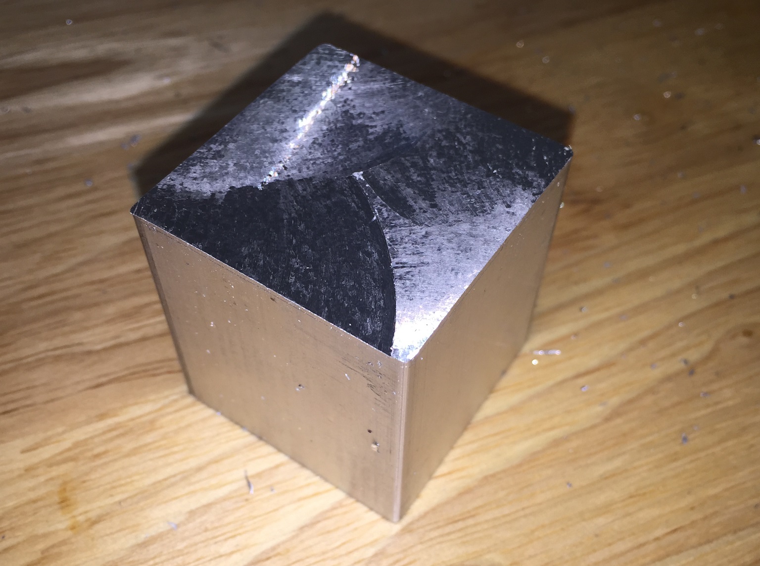
I set the stop on my fence to 39mm from the blade, and then clamped the bar to my miter fence, so I could just push the fence, and keep my hands well away from the blade. I push the fence and bar through the blade, stopping before the blade would start cutting the fence (I marked that point in pencil so I could easily stop in the right place). Then I unclamped, rotated the bar 90 degrees, and repeated this process four times. When complete I had a rough sawed piece of bar about 38mmx38mmx39mm.
*What ever you do, don’t attempt use make this cut using a rip fence, it will kick the aluminium cube back right into your face, probably knocking all of your teeth out. Also make sure you wear eye protection.
Measure the rough block and find the longest dimension. If the sawed surface is uneven, pick a spot to measure and mark it with a pencil or scriber, and use the same spot later to zero the bit height.
You should update the stock in Fusion360 on the “Face Blank” step. Make the largest dimension on the Z axis. Now go to the Face operation, and set the “stock to leave” option to about .7 mm. This should be smaller than the difference between the smallest dimension of your rough and 37mm the target size of the cube. With these settings, have it generate a toolpath and G-Code for the “Face Blank” step. Make sure you use the generic GRBL post processor.
Using this toolpath, you will mill the first three faces of the rough cube.
Go back to the Face operation, and turn off the “Stock to Leave” option, and generate the toolpath and run the post processor to generate gcode, save this gcode file with a different name, you will use it to face the other three faces of the cube.

You will need to set up a vise or some kind of fixture to hold your cube. You want to have it set up so the origin will stay in the same place as you rotate the cube to do the different faces. The unmoving jaw of the vise can be one fixed reference, for the other attached a step clamp to the side of the vise that I could push the aluminium block against. (You could probably also use a jaw stop.)
I also added a clamp on the other side that combined with a bit of MDF will keep the block from being able to slide along the X axis when the cutter is applying large amounts of force.
The working coordinate origin we will be working from is the upper left corner of the block, on the top side.


60 minutes
Place the rough block into the vise with the sawed face on top. (Z should be your longest dimension.) Make sure the block is pushed up against the stop you added. Also add some MDF or something to wedge the other side against a clamp so that the block cannot slide in the X axis. Finally make sure the bottom of the block is flat with the bottom of the vise as you tighten it. It may help to strike the block with a rubber mallet as you tighten the vise to make sure it is properly seated.
Install the 1/4" bit into the collet and zero the bit to the upper left corner. To get the bit zeroed, I run the bit onto the side of the block with the Z position below the top. The slowly move the bit along the X or Y axis with the jog controls so it is just touching the side of the block, but can still spin freely. Then you want to zero that axis, but offset it for the radius of the bit. If it is a 1/4" bit, the radius is 3.175mm. So use the G-Code command G92X-3.175 if you are on the X axis, and G92Y3.175 if you are on Y. (remember the origin is on the upper left side, so that is why Y has a positive offset). Zero the Z axis by bringing the bit down on the top of the block. Put a piece of paper on the block, and slowly lower the bit until the paper is firmly clamped between the bit and the block, then zero out the Z axis.
Raise the bit to a safe location, at least 5 or 10 mm above the block, with X and Y close to the work origin. Enter a G-Code command of G28.1 to set the safe position. The Fusion 360 programs will return the cutter to this point between steps.
Now check that your block is securely clamped, your bit is installed, and the cutter is in a safe location. You can start the spindle and start the first facing G-Code (the one with the “Stock to Leave” set to about .7mm). This will take about 1mm off of the block in one or two passes (depending on if you have a finishing pass configured), and leave a clean flat surface.
During cutting you may want to add some cutting fluid to keep the bit lubricated. I found this helped some. If you have a misting system for applying coolant you can use that, but it isn’t a requirement. You should also watch the cut (wear eye protection), and periodically use compressed air to clear the chips from around the cutter.
If the spindle is properly trammed (square with the Z axis), you should have a nice flat face with a characteristic burnished surface pattern. If you are a little out of square, it will leave ridges that you can feel with your finger.
After the first face is complete turn of the spindle, loosen the vise, and rotate the block to another face. Tighten the vise, turn on the spindle, and run the program again. The work coordinates you set for the last face should still be good. Use this first G-Code program to mill three adjacent faces of the block. These three faces should also share a single corner (don’t mill any opposing faces).
Now repeat with the second G-Code program, the one with the “Stock to Leave” option turned off. Keep the same work coordinates. This program will mill the opposite faces of the three you already milled, and you should end up with a perfect 37mm cube.

90 minutes
Now for the hard part.
Use fusion 360 to generate the G Code program for the “Completed Face” setup. This setup has the stock size set to the perfect 37mm cube you produced in the last step. You can keep the X and Y work cordinates from the last step, but you will need to rezero the cutter’s height to the top of the cube from the last step.
This program pretty aggressively cuts by boring out the center of the face, and then side milling to expand the hole. This will put a lot of force on the work piece and the spindle, so it is very important to make sure that everything is securely clamped into place. Also make sure your belts are tight on the X-Carve and secured (I used zip ties), otherwise they may slip under the force. Even if your belts have never given you trouble before, this will apply a lot more force than cutting wood or plastic, or even aluminium at short depth of cut. Also this cut will probably be beyond the ability of the stock 300W spindle, so if you are using that, you may need to modify the settings in Fusion 360.
Go ahead and start the cut, keeping the chips cleared, and applying cutting fluid as needed. (if you use an oil based cutting fluid, it will produce smoke as it burns)
The program will pause after the hole as been hogged out. At this point you should change the bit to the chamfer bit. (I usually put a rag or cloth under the bit when I change it so if it falls, it won’t break.) Remember to turn off the spindle before you start changing the bit, or put your hands anywhere near the block. The VFD spindle can be so quiet that you may not realize that it is still on. Once the chamfer bit is in place, re zero the Z axis to the top of the block, raise it to a safe height and restart the spindle. Then you can restart the G Code program. It will chamfer the edges of the block and the stepped hole. For the chamfer to be even it is very important that the block was placed squarely in the bottom of the vise, and the chamfer bit was accurately zeroed to the top of the block.
Once the chamfer is complete, turn off the spindle, and change back to the 1/4" endmill. Also loosen the vise and rotate the block to another face. Tighten the vise, and then re zero the height of the endmill to the top of the block. You can continue to use the same X and Y work coordinates. You may also want to use a chip brush to clear the chips off of the vise. Also make sure the V wheels, idlers, and pullys on the X and Y axis are clear of chips, and the v wheels on the Z axis are clean. Use the compressed air to clean them off.
Restart the program, and repeat the process until all six faces are complete.


The chamfered edges of the turner’s cube should already be fine. However the points where the holes intersected to create the edges of the nested cubes will probably still have some jagged edges. You should use a needle file to break those edges and clear the jaggs from the corners.
You can use compressed air, and then a rag to clean off any remaining chip and cutting fluid.
You should now have an almost perfect turner’s cube made with your X Carve. This is a great little toy that really shows off the capability of the X Carve.