
Numbered D12 (Dodecahedron) Coin Bank in 1/8in acrylic, ~6 & 1/2inch (16.6cm) tall, with miter edges, & integral release plug. Created for Inventables’ “Easel Power Hour” Challenge.
_
Designed entirely w/ Easel for a 750mm+ X-Carve with a cut time <1hr, (not including assembly & drying time).
Additional Materials:
Optional Materials
Notes:

Note:
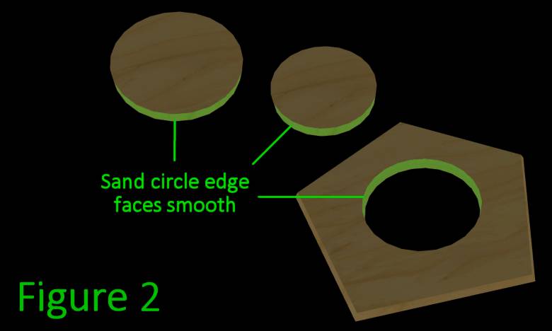
If your acrylic’s ‘front’ has a protective film, painters tape + CA glue is the preferred hold down method. If it doesn’t, double sided tape should be used since CA glue vapors might cause surface clouding. You can use tabs instead, but this will probably take more sanding effort than it’s worth.

60 minutes
1 Note:
When assembling the Sanding Jig, if the protective film is plastic, you can try leaving it on to test if the acrylic glue will bond to it. if it doesn’t then you can leave it on further parts until instructed to check that it’s removed (this can help avoid marring or spills of glue while working).
2 Note:
During assembly of the Sanding Jig is a good time to test if your sandpaper is fine enough to get a clear acrylic bond. You can lightly sand the grooves and flat edges of the semicircles before gluing. if it comes out less than perfect you should use a finer grit on the rest of the parts.

20 minutes
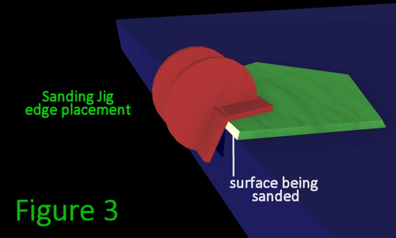
3 Note:
You may be wondering, “why didn’t we just cut the exact angle to begin with?”. If we try to cut it as a contour shape we won’t get as clean of an edge (bad for gluing), and that method takes more time than the sanding does. It’s possible to use adjustable v-bits but they are bulky and not quite precise enough, and are very expensive (as are custom v-bits). It may seem like a small amount, but it really makes a difference in glue bond clarity and strength. For thicker pieces the difference results in larger visible gaps on the outside edges if not corrected.

The actual work time of this section is short, but minimum glue drying times may be longer depending on different factors


